The operating principles of car brakes
We all know that when the car is on the road, as long as you brake, the car will slowly slow down and stop. So what really happened when you brake? How is the pedal force from your foot transmitted to the wheel? Is the leg power amplified large enough to be able to brake an enormous car? This article will work with you to learn the basic principles of brake systems in cars to answer the above questions.
>>>Operation principle of the clutch
Brakes are listed as car safety systems. Of course, not only cars but also any means of transport must have a system to help reduce speed and stop at the discretion of the operator. On most cars, we will encounter the two most basic types of brakes, the main brake (usually hydraulically operated). In the framework of this article, we will examine the first type of brake, the main brake, the hand brake will be studied further in another article.
The basic principles in a braking system
First of all, the problem is that if only using the driver's force, it is impossible to stop a car that is much bigger and heavier, so the brakes are extremely necessary. When you step on the brake, the force is transferred from the foot down to the brake mechanism through the fluid pressure that is passed through the hydraulic hose system. In order to increase the braking force to the required level to stop the vehicle, the braking system used two power assist mechanisms: lever and hydraulic. Next, the braking force will be transmitted to the wheel as friction force. At the same time, the wheel will also transfer that force to the road surface in the form of friction to help the car stop.

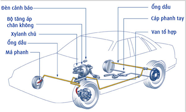
Diagram of the main components of the car brake system
Before we start investigating the details in the brake system, we will summarize the three basic principles of a car braking system:
- Lever
- Hydraulic (oil brake), vacuum, pneumatic or combination
- Friction
Basically, the hydraulic and gas structure works similarly so I will choose to describe the hydraulic type so that you can imagine more easily. At the same time, most cars today use hydraulic brakes primarily. Some vehicles also use a combination of compressed air.
Lever and hydraulic structure

Leverage and hydraulic
In the illustration above, an F force has been applied to the left end of the lever. The left side is 2 times longer than the right, so the right upward force is also twice as large as the left thrust. If you change the force set to the left, the multiple also changes accordingly. That is the basic principle of leverage that we all know. And when combining the leverage idea with the hydraulic structure, we get the essence of amplifying the brake force in the car.
Basically, the braking power system in a car has a fairly simple way of operation: The force is transmitted from the driver's foot to another point through a liquid that cannot be compressed, usually oil. Below is an illustration of a simple hydraulic system.

2 pistons (red) are fitted to fit inside the oil-filled cylinder
As you can see, the 2 pistons (red) are fitted just inside the oil-filled cylinder. 2 cylinders that are connected together by a conduit are also filled with oil. If you push a piston down, the force will be transmitted through the oil and lead to the cylinder on the other side making it move up. Since the nature of the oil inside the duct is very compressed, almost all of the force is transferred back and forth between the two pistons. At the same time, the advantage of hydraulic structure is that we can fabricate pipelines in any shape and size to suit the installation needs of the vehicle.

Just change the size and capacity of the cylinder, the force will be transmitted according to the required rate
At the same time, we can also split the pipeline, so that we can use 1 piston master to transfer more piston. And we started to see, pedaling at 1 point but the braking force was distributed to 2 wheels. Therefore, as long as the engineers change the size and capacity of the cylinder, the force will be transmitted at a required rate.

Figure depicting 2 piston size
With the image above, suppose the left piston has a diameter of 5.08cm and the right side is 15.24cm. With simple calculations, we will have the cross section of the left and right pistons of 20.26 square centimeters and 182.41cm square respectively. The right cylinder has a section that is 9 times larger than the left. That means that any force acting on the left piston will be multiplied by 9 times in the right cylinder. For example, if you apply force to push down 100N into the left piston, the right piston will move upward with a force of 900N (ignoring friction and other drag). At the same time, you just need to move the left piston down to 22.86cm, the right piston will be raised to 2.54cm.
Principle of friction

The above figure is that both blocks are assembled from the bricks, but the right block is 4 times heavier than the left
In theory, friction is a kind of drag that occurs between material surfaces to counteract the tendency to change relative positions between two surfaces. In a simple example above, both blocks are assembled from the bricks, but the right block is 4 times heavier than the left. Of course, you will need more force to push the right block to move. Why so?

Each type of material will have a different microscopic structure
Although the surface of the bricks is very smooth when viewed with the naked eye, but when magnified under a microscope, you will see the surface of the bricks is not as flat as you think. At the same time, bricks also have weight and are always pulled down vertically by the Earth. Therefore, the heavier the brick, the bigger the weight plus the rough surface will help it stick to the surface.
Each type of material will have a different microscopic structure. Typically steel will slip on steel easier than sliding rubber onto rubber. Therefore, here we will have the concept of sliding friction coefficient, which describes the ratio between the magnitude of the sliding friction force of the material and the gravity acting on the object. Suppose if the sliding friction coefficient is 1, you need to use 1 force of 100N to push an object with 100N weight. But if the sliding friction coefficient is 0.1, then you only need to use 1 force 10N to push the 100N object.
At this point, we have grasped the basic physical principles of braking system operation. Next, we will easily examine the operating principle of a specific brake system.
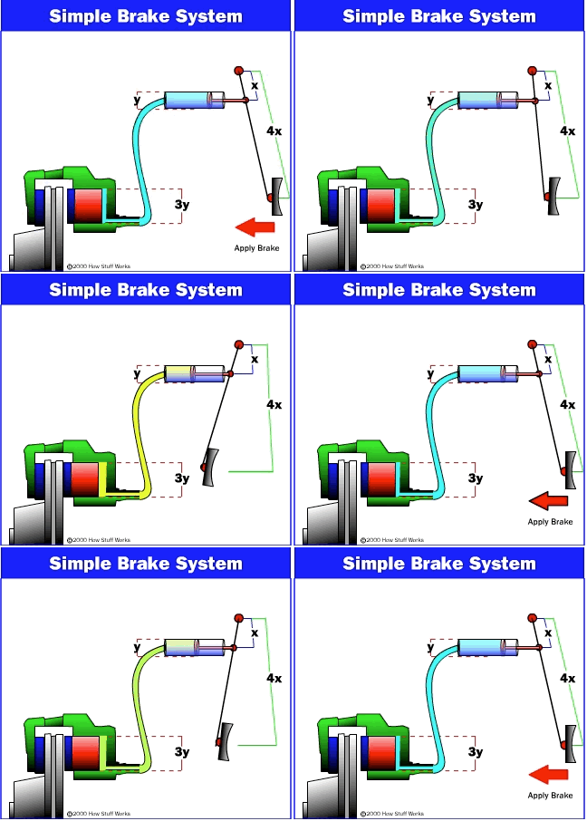
Basic brake system

Figure depicting the brake system
In the illustration, you can see that the distance from the brake to the fulcrum (x) is 4 times longer than the distance from the fulcrum to the cylinder (4x). Therefore, the brake pedal force will be multiplied by 4 times when transmitted to the cylinder. At the same time, you also realize that the diameter of the last cylinder (3y) is 3 times larger than the first cylinder (y) which means that the section is 9 times larger. Combining the entire system, the driver's braking force will be multiplied by 36 times. If you apply a force of 10N to the brake lever, a force of 360N will press on the brake pads.

Brake system with master cylinder and valve combinations
When I came here, I also wondered what if oil leaked out? If the oil leaks, it will of course be that there is not enough liquid in the cylinder and the oil pipe leads to the brake system not working. To overcome this, engineers built a brake system with master cylinders and valve combinations. Let's find out.

The master oil cylinder is divided into 2 interconnecting chambers and will provide pressure for both oil piping systems
As you can see in the picture, the master oil cylinder is divided into 2 interconnecting chambers and will provide pressure for both oil piping systems. When you step on the brake lever, pushing the first piston moves forward and the internal oil pressure increases. Then, the pressure between the first piston and the second piston will push the second piston forward. Meanwhile, the oil will be pushed normally to the brake. In the case of oil leaking at one of the two tubes, the pipe will not be able to maintain the original pressure but still ensure that the pressure in the pipe remains enough to transfer to the brake mechanism at the wheel. Meanwhile, the driver must press the brake lever harder, however, the car can still brake safely.
At this point, we were able to understand the basic principles of the operation of the brake system in general and brake on the car in particular to answer the questions raised at the beginning. Of course, the brakes on cars still exist many other problems such as sorting and pros and cons of each car brake system as well as brake assist technologies. However, in the framework of the article, I would like to conclude at the basic principle, appoint you in other specific articles about each brake system. Thank you for following the article. Have fun and drive safely!
Reference: SDT, Overdrive, Auto (1), (2), Bosch
- Wireless Brake
- Note when using motorcycle disc brakes
- Operating principle of helicopter
- Elevators and things you may not know yet
- District school girls invent electromagnetic brakes
- The 5 most basic principles of health and exercise
- Bicycle brakes generate electricity
- The '5 correct' principle in drug use
- What to do when a car loses its brakes or loses control?
- How does an automobile engine work?
- 7 golden principles that help live long
- Passenger car support takes brakes on the pass under a scientific perspective
 'Barefoot engineer' invents a pipeless pump
 Process of handling dead pigs due to disease
 Radiometer
 Warp Engine: Technology brings us closer to the speed of light